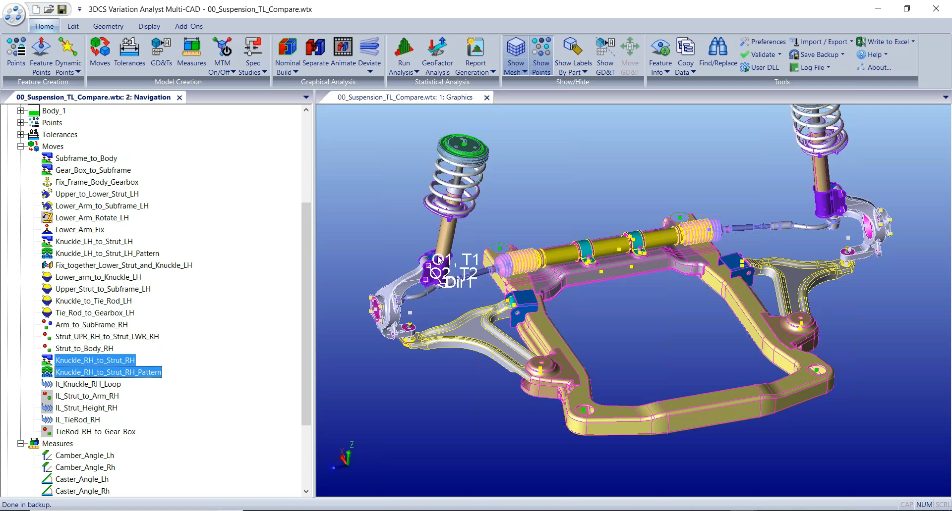
3DCS Variation Analyst Multi-CAD is a stand-alone tolerance analysis software solution that simulates product assembly and part tolerance 3D stack-ups through Monte Carlo Analysis and High-Low-Median (Sensitivity) Analysis.
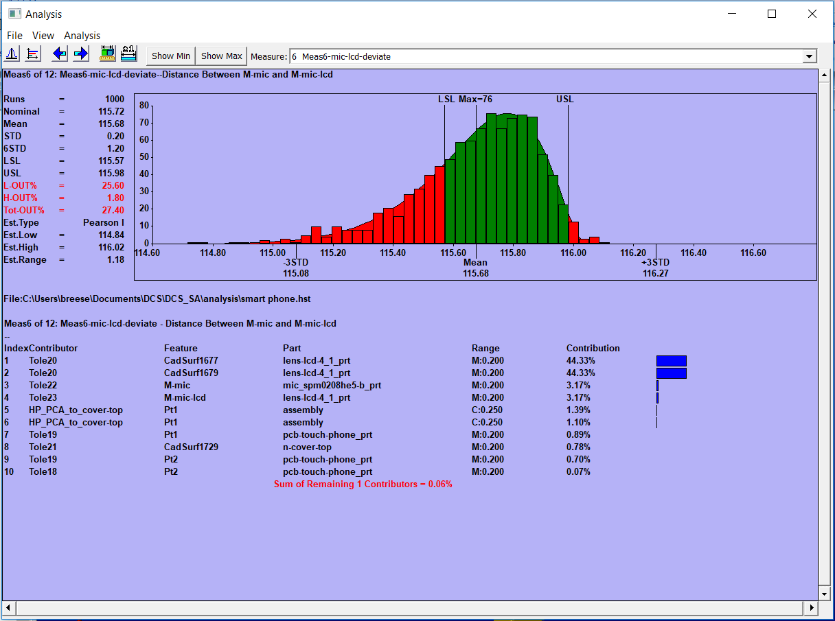
3DCS Multi-CAD simulates part and process variation with Monte Carlo Simulation to give statistical outputs showing the estimated percent of products that will be out-of-spec, the primary contributing tolerances and parts to variation issues, and specified statistical measures such Cpk and Ppk.
3DCS Multi-CAD uses TransMagic translators to analyze models from any CAD system. This allows companies who juggle multiple CAD systems to use any CAD file for their tolerance analysis.
3DCS Variation Analyst Multi-CAD uses three methods of simulation;
2. High-Low-Median (Sensitivity analysis)
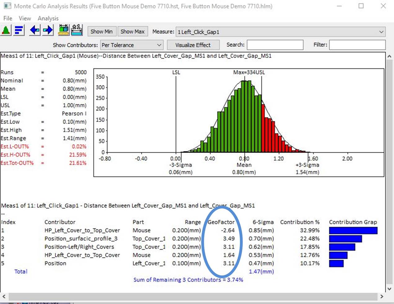
3. GeoFactor (RSS equation) Analysis
By accurately modeling the assembly, you can see how both the assembly process and the part tolerances contribute to the product's overall variation. Together, this creates a virtual prototype that can be used to make decisions about design changes and tooling while reducing non-conformance that leads to scrap and rework.
Simulating products in a digital environment gives engineers the ability to account for variation in key areas; reducing rework, non-conformance, and scrap at final assembly early in the design phase when changes are least expensive.
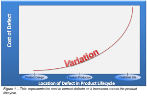
In addition to this, specifications deemed less critical can be relaxed, increasing tolerances and allowing the use of less expensive manufacturing processes. Creating 3-dimensional tolerance stack-ups let engineers know where to focus when measuring and designing, and the ability to create what-if studies allow them to determine solutions that include both process and part tolerances to keep quality high and costs down.
How does 3DCS help you reduce lead times, scrap, and rework?
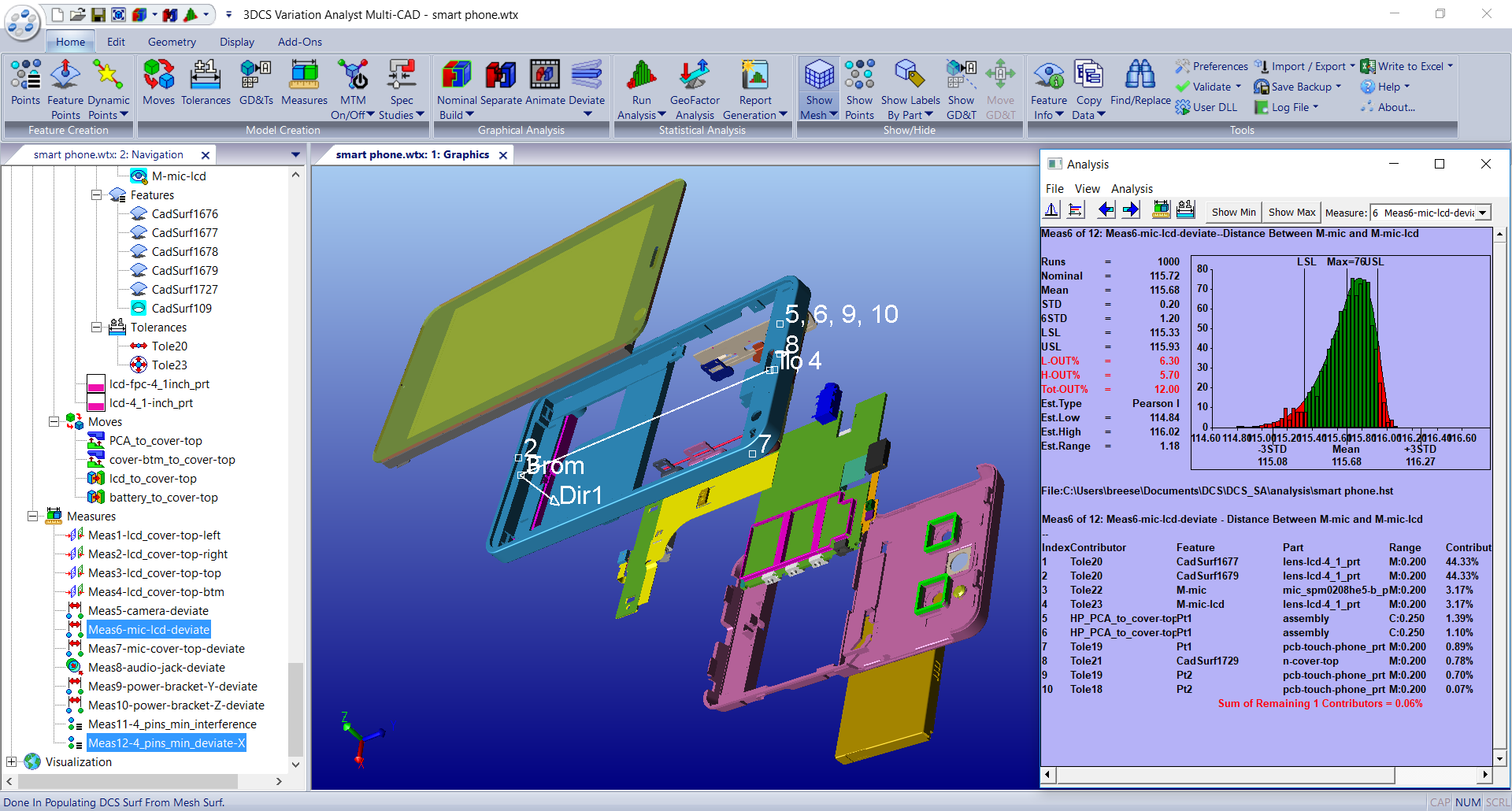
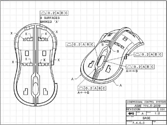
3DCS Multi-CAD can use PMI (Product Manufacturing Information) and embedded GD&T from your CAD to instantly tolerance your parts. Simulate the build to validate your tolerances, then make adjustments to optimize for cost, quality, and variation control. Once complete, push your tolerances back to CAD and update your models.
Value:
Create life-like images of your product showing worst case scenarios to determine the visual impact of variation stack-ups. Use these studies to determine maximum and minimum tolerances during design and communicate with engineering. Once engineers have determined the manufacturing tolerances, recreate the studies to see how your actual product will look with worst case tolerance stack-ups. These studies together help you improve the Perceived Quality of your product as well as your build quality.
Value:

Find the source of variation, honing in on either particular part tolerances, or processes. Many times the source of variation is in the assembly process and the solution does not require the changing of tolerances. This can give engineers the ability to improve quality without having to make costly tolerance adjustments. In addition, tolerance and process changes can be made in the model and simulated to find optimal conditions to get the greatest increase in quality at the lowest cost.
Value:
Use reports and measurement plans to communicate results across the organization. Detailed engineering reports communicate with other design teams the inputs and outputs of the model so that the results can be repeated and understood. Management Reports communicate the key outputs to managers to support key decision making. Measurement Plans communicate important areas and particular points to be measured at the plant or CMM room to control variation and watch for out-of-spec and non-conformance conditions.
Value:
Find the source of variation, honing in on either particular part tolerances, or processes. Many times the source of variation is in the assembly process and the solution does not require the changing of tolerances. This can give engineers the ability to improve quality without having to make costly tolerance adjustments. In addition, tolerance and process changes can be made in the model and simulated to find optimal conditions to get the greatest increase in quality at the lowest cost.
Value:
Determine the geometric relationship between tolerances and the overall assembly. How much of an effect will changing particular tolerances have on the product's dimensional quality?
Daniel C. da Silva
Embraer Tolerance Analysis Team Leader, Embraer
Learn more about 3DCS and upcoming webinars from the DCS Blog - Engineering Talk